AUTOSAR – Compliant ECU Design for Electric Vehicles
13 December 202112 June 2018 | Software
This article describes a few steps required for the design of automotive components, focusing on ECUs and illustrating some of the industry-standard tools required to generate AUTOSAR compliant code. Learn more about Fortech’s Automotive Software Development Offering.
AUTOSAR – compliant development of ECU for electric vehicle
The Automotive Open System Architecture (AUTOSAR) is an industrial alliance in which a number of Original Equipment Manufacturers (OEMs), component suppliers and hardware vendors have established a de-facto standard for electric and electronic architectures of vehicles. It focuses first on the system and it also specifies the ways of integrating software components (SWCs) using a predefined and standardized software layer.
Nearly 15 years since AUTOSAR’s first release, the most recent specifications about developing AUTOSAR compliant code are provided in [Aut14]. A major advantage is that all application software running on an Electronic Control Unit (ECU) is hardware independent, through an abstraction layer and an AUTOSAR runtime environment.
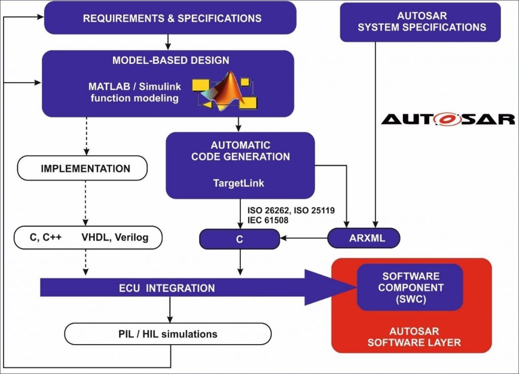
Figure 1. Model-based design for generating AUTOSAR SWCs
Considering the large scale of complexity from automotive systems, distinct safety integrity levels were specified for both hardware and software. The code needs to comply with ISO 26262, which specifies the functional safety for road vehicles. Since the specifications are very comprehensive, parts of it have been adopted in other transportation systems, such as railway, marine or avionics. Another standard belonging to this family is ISO 25119, defining safety systems for agriculture and forestry vehicles. General regulations on the same topic, applied to industry, are given in IEC 61508.
As current embedded systems must handle millions of code lines and taking into account that the functionality of the controllers needs to be well understood at signal level, the traditional way of constructing embedded code – starting from the main() function – has become obsolete. Therefore, it has become preferable for the engineer to focus on functionality, physical phenomena modeling, module interfacing, and the overall behavior of the system.
The blocks with white background and connected with dotted lines in Figure 1 illustrate the traditional way of developing code, which can be flashed on microcontrollers or FPGAs (field-programmable gate arrays). The difference is that the effort for reaching ISO 26262 compliance is worth only for very small systems.
ECU for electric vehicle and ECUs can be found in any modern car, the OEMs preferring to split function development across several specialized suppliers. An ARXML (AUTOSAR XML) file is provided to them with the SWC description which contains specifications for the application, communication interfaces, access to sensor signals available from the ECU, and many others. All these will simplify the software integration of the functions, developed often across continents, integration that relies on the compatibility provided by AUTOSAR. The definitions of such components, via ARXML files, are found in manufacturing, supply chains, and product lifetime management in the automotive business.
The software components make possible the definition of complex systems in terms of smaller subsystems, simplifying the tasks of combining them to run into one ECU, and of integrating multiple ECUs into a network. Functions which are already tested and validated can be reused, reducing the development effort for future products and allowing backward compatibility.
After performing the integrations on the ECU (see Figure 1), Processor-in-the-Loop (PIL) and Hardware-in-the-Loop (HIL) simulations can be done by running the resulting code on the target. Their role is to refine the requirements and specifications on one hand and to improve the simulation models on the other hand. What they imply and how they differ is described below.
This article enumerates typical phases which the development implies when the target is automotive software, starting from modeling tools, electric motor particularities, analysis models for defining its parameters, and ending with real-time and Hardware-in-the-Loop simulations. It may be useful for component or system designers, who want to better understand the context of their work, as well as the means which were used to get their input data. The latter is often given in forms of lists and tables, which do not always allow the tracing of a specific parameter back to its roots. Providing an approach that is based on modeling physical phenomena and validating it using complex software such as the finite element method, may help to get a bigger picture over model-based design in this respect.
V-model particularities for software development
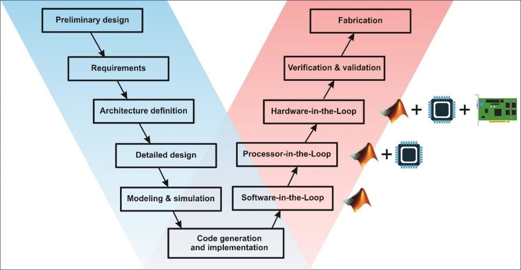
Figure 2. Particularities of the V-model – SIL, PIL, and HIL
The product development diagram illustrated in Figure 2 has its roots in the model-based design, with an emphasis on the embedded and IoT industries. Compared to the general case of the V-model software development, its particularity is given by the presence of the Software-in-the-Loop, Processor-in-the-Loop, and Hardware-in-the-Loop blocks. Their role is briefly described in the following sections, the complexity increasing while approaching the manufacturing phase.
The preliminary requirements and specifications help to identify the environment and system behavior models, while the functionality is not necessarily tied to specific hardware. The first simulations performed will contribute to their refinement, meaning that they will become more explicit towards certain application cases. Integrating the requirements in the simulation models is critical for efficient development.
The definition of the system architecture should make a modular design possible, a hardware abstraction layer being expected in most cases. The key control parameters of the system should be identifiable and traceable at this point.
The detailed design helps to integrate the component and functional models, which are often tied to specific algorithms and numerical methods. The effective use of the control toolboxes improves the overall design; an illustration of this improvement is that stability issues in the complex frequency domain can be overcome starting with this phase. The definition of software and hardware interfaces, analysis of subsystem interaction, and choices for platforms and hardware also become possible. Up to a certain extent, the software and hardware development can be done in parallel. Industry-standard modeling and simulation tools allow automatic code generation from the block diagrams, the engineering work focusing here on the numerical accuracy of the results. These are still independent of the target platform or a specific programming language.
In AUTOSAR terms, the software “implementation” is done mostly by automatic code generation tools. When this happens, the developer has little to no control and human readability of the generated lines of code is not always possible because being compliant with ISO 26262 has higher priority. Another option would be to start all the implementation from scratch, at the cost of constantly checking all ISO-compliance levels after adding every couple of lines of code. This approach was proven far from efficient when talking about millions of lines of code which get in controller units used in the automotive and aerospace industries. In such cases, the developer simply begins focusing more on the coding than on the system functionality which must be achieved. High-end automobiles currently have around 10…100 million lines of code, and not being compliant with the required safety levels is unacceptable.
Before starting any numerical simulation for electric motors, a good practice is to make use of an analytical solving method, if applicable. The parameters which are idealized in analytical models can be usually accessed via numerical simulation blocks, making this type of equivalence straightforward in one direction.
Development techniques for embedded systems – SIL, PIL, and HIL
Software-in-the-Loop (SIL)
The SIL generated code runs on the PC where the simulation takes place. This phase requires just the simulation model and is hardware independent, the focus being on software interfaces and numerical results. The software requirements and specifications can be analyzed and checked here, the first phase of requirements refinement taking place during SIL simulations.
A few items typically used in model-based design for battery electric vehicle (BEV) and hybrid electric vehicles (HEV) are given below. Simscape is an extension of Simulink designed to model multi-domain physical systems. It is used by system engineers to define and build models representing the physical structure of the system.
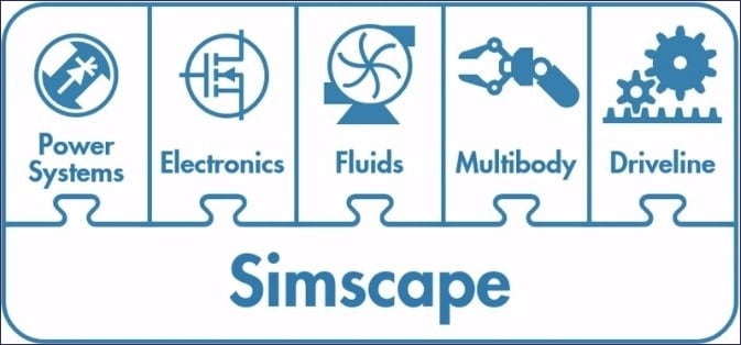
Figure 3. MathWorks Simscape family of products
A rich set of electrical components is available in Simscape Electronics [Ma182], such as passive devices, semiconductors, logic gates, sensors, various types of electric motors and actuators. Simscape Driveline [Ma181] includes components for simulating rotational and translational mechanical components. Internal combustion engines, gears, clutches, belts, pulleys, and tires can be found in Simscape Driveline. Power converters and electric drives are available through Simscape Power Systems, while engine cooling systems via Simscape Fluids. The entire suite allows the generation of C code from simulation models, which can be used in PIL and HIL environments. Simscape also provides valuable means for rapid evaluation of designs, with interactive analysis plots. In short, it is a simulating plant and controller in one tool which allows engineers to understand and optimize the performance of the entire system.
Processor-in-the-Loop (PIL)
Supplementary to a SIL simulation, Processor-in-the-Loop requires the generated code to be executed on the target platform (MCU), making possible a first estimate of the performance on target. Runtime metrics that were not obvious in a SIL simulation, due to the higher computing power of a PC, have a first chance to be noticed here. PIL results should detect platform-related bottlenecks and insufficient hardware capabilities; otherwise, it validates the performance on the MCU. Of special interest are the benchmarks, memory content view, disassembly options, hardware interrupt monitoring, waveform analysis, thermal effects and electromagnetic interferences, among others.
Hardware-in-the-Loop (HIL)
Due to its complexity, developing ECU software on prototype vehicles is time and cost intensive. Considering the implications of a severe powertrain fault, safety played a key role when engineers looked for other design methodologies. Having decades of experience with the internal combustion engines, a strong level of knowledge already existed while switching to other types of motors – hybrid electric and battery electric.
Developers rely nowadays on model-based design methodologies, focusing on the operation of a specific component and the overall functionality, rather than writing code from scratch or worshiping a specific programming language. OEMs and suppliers from the automotive industry agree that Hardware-in-the-Loop systems have become the de-facto standard in software engineering, electronics, and mechatronics development. This approach has become mandatory when building large failsafe systems, related to transportation, aerospace, defense, etc.
ECUs are often available sooner than the rest of the vehicle components, enabling a large amount of the functionality to be known before building the car. It is a common practice for suppliers to use HIL systems for validating their individual subsystems and provide their simulation models in a standard format.
HIL systems can be used for developing and testing a simple software function, the full set of hardware and software ECU for electric vehicle functionality and large systems containing mixed types of control units (motor, automatic transmission, stability, etc.). The ECU is given electrical signals, which are the result of a real-time dynamic simulation model. The output signals that it sends in response are read as input variables by the real-time model. In the frame of this approach, typically a computer running Simulink [Ma183] executes the real-time system models. Therefore, the ECU can be operated in a laboratory environment exactly as it were in a real vehicle. Furthermore, such a test bench allows real-time access to all signals that are difficult to measure in a real system. Operating points and corner cases that are almost impossible – or too risky – to recreate in a real system can be handled in an elegant way using HIL simulators. A simple example would be testing the Electronic Stability Program (ESP) while driving at full speed. Single and multiple faults can be injected during simulation, covering the most improbable real-life situations. The costs for fixing errors are much lower if they are found in the early design phases.
Depending on the used setup, extended simulation components are available from dSPACE and are described in [Dsp16].
AC vehicle motors
Most of the above descriptions are not tied to any specific motor type – internal combustion engine, hybrid electric, battery electric etc. Considering only battery operated motors, a few design considerations are described in the following paragraphs, providing an overview of the modeling methodologies.
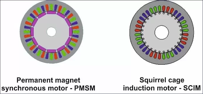
Figure 4. Two configurations of AC motors. The rotors are in the center in both cases.
Two of the most used types of AC motors in electric vehicles are the permanent magnet synchronous motor (PMSM) and the induction motor, which has a specific configuration, the squirrel cage induction motor (SCIM). The stator generates the rotating field for both of them. In the PMSM, the rotor follows the rotating field synchronously, so that the speed of the stator rotating field equals the speed of the rotor at any time. In the induction motor, the current induced by the stator rotating field creates a rotating field in the rotor. In this case, the rotor follows the stator rotating field asynchronously, at a lower speed.
Finite element approach for electric motors
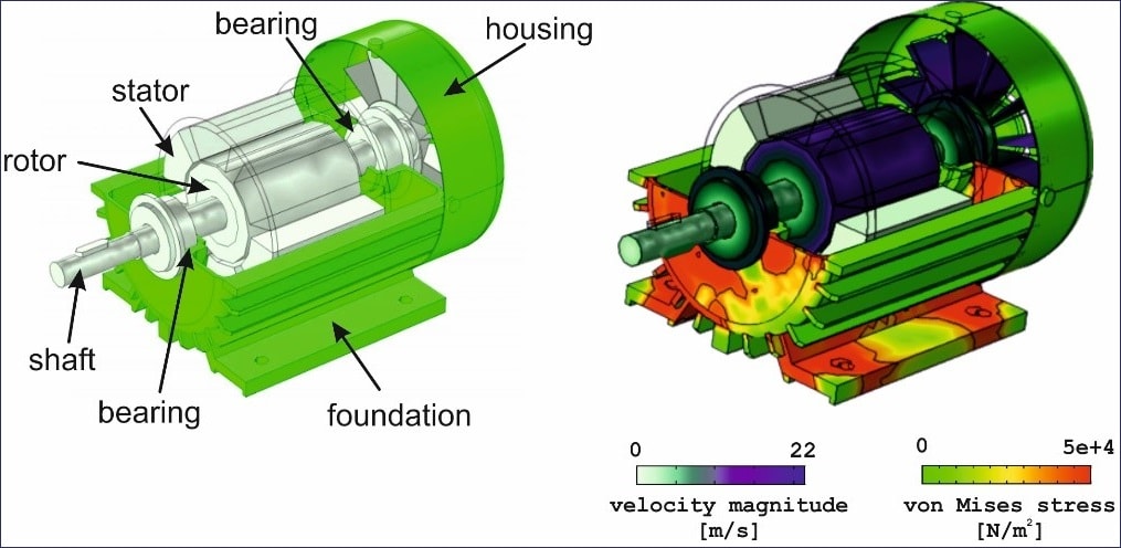
Being rotating machinery, motors like the ones mentioned above are susceptible to phenomena that can only be estimated numerically or cannot be directly measured over the interval of interest. Magnetic flux density, magnetic noise, rotor speed, torque, and losses, stator current and mechanical stress, step changes in load torque, vibration spectrum, transient rotational effects, temperature influences, acoustic noise, can all be analyzed using the finite element analysis method (FEA) [Com16], [Com17], [Pec15], [Koc17], [Wil14]. FEA is the industry standard for simulating coupled effects, electromechanical and electromagnetic phenomena in a self-consistent manner. Most of these parameters will be relevant for the software development phase, as long as they will define the simulation model which will be further used to generate code compliant to specific safety levels. The code running in powertrain components must comply with automotive safety integrity levels (ASIL) from the upper range. Therefore, knowing where such parameters originate or their interdependencies, can only improve the insight in this field.
Figure 5. Induction motor components and FEA of stator stress and rotor velocity magnitude. Source: [Com17]
The following use cases are just a few illustrations of using finite element analysis for electric motors.
- knowing the geometry, the materials composition and the electrical specifications, several operating points need to be checked before powering the motor. For example, performing simulations between -40…+85 °C is faster and does not require a temperature controlled chamber. All electrical machines generate losses in the form of heat, especially at high revolution speeds. To extend the life of the machine, the heat must be removed in an efficient manner from the system. Knowing that ratings depend on the thermal capability of the system, performing a thermal analysis is mandatory when designing new motors;
- starting from an existing design, one or more parameters must be changed to follow a goal function. Using iterative simulations, a near-optimum set of new parameters can be introduced in this respect. For example, changing only the material alloy of the rotor windings for lowering the losses would fall in this case. Even if the goal is reached, this change may introduce side effects such as very different dynamic impedances, with a lower overall performance of the motor;
- the given set of design parameters is incomplete, and a specific parameter needs to be estimated as well as possible. Using step parameterization rules and setting an interval for the monitored values, the value can be obtained indirectly without spending hours doing measurements on a test bench. For example, the vibration spectrum is not specified and we need to be sure that attaching the motor to a well-defined gearbox will not add unwanted effects;
- obtaining simulation parameters which cannot be measured directly by conventional means, which will later help create an accurate Simulink model for the motor.
Closed loop models for electric motors
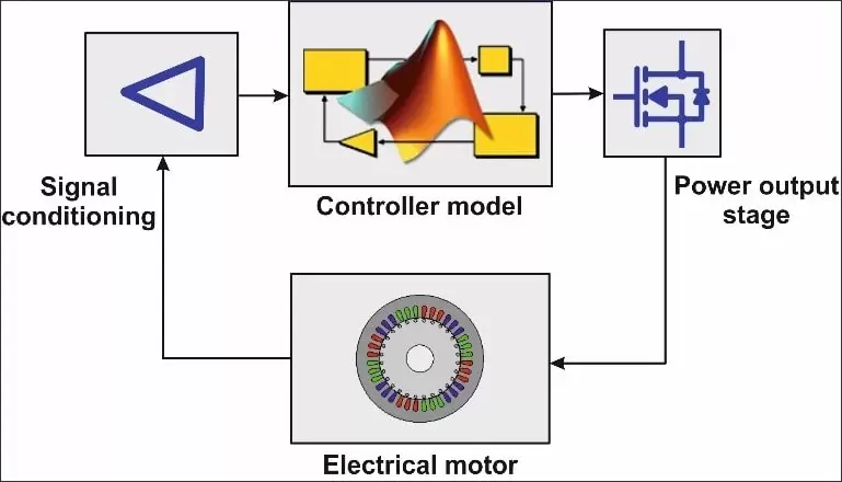
Figure 6. Simplified control model for an electric motor
Figure 6 contains a simplified closed loop diagram with the blocks required to control an electric motor. The signal conditioning and power output stage act as inputs and outputs for the controller, respectively. The signal conditioning module has the role of adapting the type and range for any measurable values from the motor in a form that the controller can process directly. The power output stage provides the current required for driving the motor as the controller logic dictates. It should not distort the shape of the driving signals and should not introduce any delay.
A simple use case would be to control the motor speed at a constant value and can be simulated with and without the mechanical load attached to the motor’s shaft.
Electric machine control
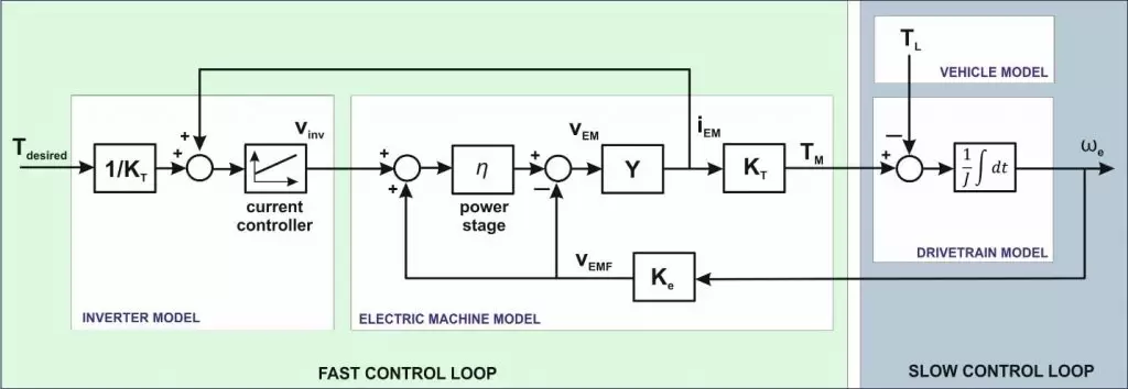
Another case, much closer to electric vehicles scenarios where load always exists, would be to control the torque by estimating the shaft’s angular speed. One of the possible block diagrams for doing this is illustrated in Figure 7, based on a generic electric machine, without using any particularities of a synchronous motor or induction motor.
Figure 7. Block diagram of a basic electric machine
The input parameter is the desired torque Tdesired, which should be applied to the motor shaft. This signal is used by three models – inverter, electric machine and drivetrain – until it produces the electromotive angular speed of the rotor, ωe. The fourth model involved belongs to the vehicle and generates the load torque, TL. The vehicle model is nonlinear and depends on included physical properties such as mass, wheel radius, rolling, grade and aerodynamic resistances, longitudinal and transversal dynamics, roll and pitch angles, road condition etc.
The last two models include signals that do not change abruptly in time, so their operation can be performed through a slower control loop, with typical values of 1-10 ms. In contrast, the inverter and electric machine models require higher performance levels and are therefore operated in a faster control loop typically based on 1-10 µs.
This diagram can be extended for hybrid electric vehicles, by simply adding an internal combustion engine model next to the drivetrain model.
The desired torque Tdesired is divided by the motor torque constant KT to obtain a current which, combined with the electric machine current iEM, will generate the inverter signal vinv. For a three-phase AC motor, there will be three such signals, each determining an electric machine voltage vEM. The electric machine admittance Y is used to translate the voltage into current, iEM. One step further, the motor torque TM is obtained by multiplying the current with the motor torque constant KT.
The drivetrain of a vehicle distributes the engine power to the wheels. In internal combustion engine vehicles, it consists of the engine, clutch, transmission gears with multiple ratios, shafts, and wheels. The drivetrain of an electric vehicle is simpler, having the engine, a transmission with fixed reduction ratio, shafts, and the wheels. Some designs deliver the power to the wheels through a differential, which allows each wheel to spin freely while providing power to both. In Figure 7, the drivetrain model compares the motor torque TM with the load torque TL, their difference divided by the rotor moment of inertia J determining the shaft angular acceleration. The torque response of an electric vehicle is much quicker than the torque of an internal combustion engine from conventional cars. The electromotive angular speed ωe is multiplied in the electric machine model with the motor electric constant Ke to obtain the back-electromotive force, vEMF.
If a very exact simulation of the PMSM or SCIM is needed, dedicated models also exist. Starting from the three-phase winding signals, using an intermediary stator fixed coordinates system, they finally rely on the d-q (direct-quadrature) coordinates. The mathematical model contains combinations of direct and inverse Clarke and Park transformations, where physical motor parameters are accurately used, such as stator per phase resistance and inductance, rotor resistance and inductance, flux linkage, load torque and moment of inertia or shaft angular acceleration.
Both PMSM and SCIM models are suitable for bilinear transforms, for solving ordinary differential equations, for variable sample times for synchronous PWM, and are configurable for delta-star connections.
More diagrams and transfer functions for electric machines and vehicles can be found in [Hod01], [Hus03], [Lar03], [Ema05], [Ehs10], [Ma181] a. o.
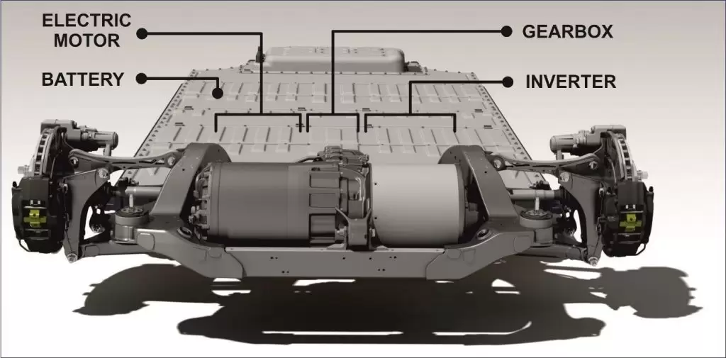
Figure 8. Powertrain of a battery electric vehicle. Source: Tesla Motors.
Figure 8 shows the powertrain of a battery electric vehicle, illustrating four main components. The battery pack is based on a multitude of single cells, organized in modules, the Li-ion technology being a very attractive choice. The power inverter transforms the DC current in AC current. The gearbox transmits the motor torque to the wheels. Any motor-gearbox system has an optimum range for its operation, being a combination of rotational speed and torque. A design goal would be to maximize this range, for ensuring an increased road autonomy.
HIL simulator for electric vehicles
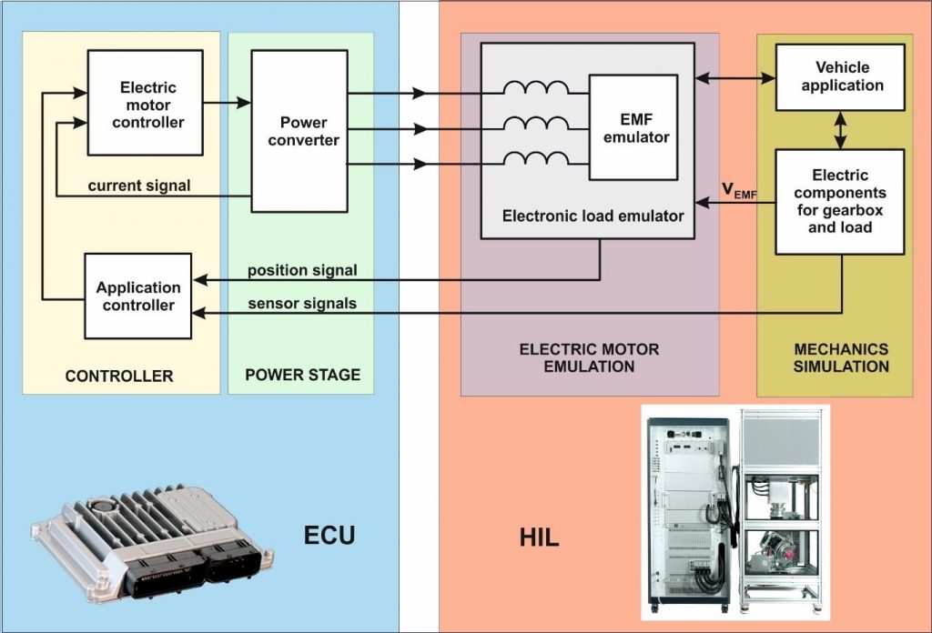
Figure 9. HIL diagram for ECU for electric vehicle
Electric motors have a more dynamic behavior than internal combustion engines, requiring ECU clock signals around 10-25 kHz, significantly higher than traditional ECU HIL applications for powertrain or chassis domains. Unlike power systems, power electronics converters rely on high frequency controlled and self-commutating switching devices. Power MOSFETs, IGBTs, SCRs and thyristors operate at frequencies in the order of tens of kHz, the required spectrum for analyzing their system dynamic effects exceeding 1 MHz, mostly due to interharmonic and harmonic superposition. It becomes clear that a Nyquist frequency of 50 kHz will not suffice for an accurate data acquisition. Given the large number of signals to be processed in real-time by the HIL, a compromise needs to be done. Many systems use a factor of 3…5 for multiplying the Nyquist value, for making sure that most system dynamics frequency content is included in the processing. Therefore, electric motor control applications are simulated in a convenient way with FPGAs. Typically, in a HIL simulator diagram like in Figure 9, the FPGA supports the motor model and the three-phase inverter model. It covers functionalities like PWM signal measurement, position/angular sensor simulation, dynamic ohmic losses in switches and diodes, as well as high rate resolvers and encoders. Besides the control of the shaft speed of the electric motor, it must also handle torque related currents in a fast control loop (see iEM in Figure 7, for example). This is why the HIL simulator must meet requirements for high power output, and current sink respectively.
On the other hand, the mechanical models and parameterization for the FPGA models are handled by a processor board. The simulation models for purely mechanical elements, such as gearboxes, reduction drives and shafts with load can be performed by programmable boards. The sensor signals read by the ECU in the HIL setup are a close match to the real ones, delivered by transducers attached to the mechanical components in a vehicle.
Three types of interfaces can be depicted in Figure 9 – signal, electrical power, and mechanical.
The controller module reads input signals like current from the power converter, position from the electric load emulator, and sensor signals from the electronic boards simulating the mechanical components.
The power converter generates the three-phase signals for being delivered to the electric motor, using the real-time information from the electric motor controller. A solution is to operate a real drive motor on a test bench, while another is to emulate the electric motor. The second option means reproducing the electrical behavior of a real motor with hardware that does not necessarily looks like one, but contains components with similar functionality, some even software configurable. Compared with the first solution, a purely electric test bench is easier and safer to operate. Tests can be run at very early development stages, even when the actual electric motor is not available yet. Its physical properties, such as inductivity, torque generation and power consumption are represented with a high degree of realism. It must also emulate accurately the electromotive force (EMF). Possible choices for electronic loads up to 800 V can be found in [Dsp18].
The power signal interface – for both ECU and HIL – needs to be defined to cover various use-case scenarios, such as gate drive signal loss or open-phase fault. They point to situations where power stage electronics is faulty or motor windings are physically interrupted. The HIL must provide flexible electronic control interfaces for covering all relevant use-case combinations. It must also allow the reproduction of open-circuits, for example via banana shorting plugs on its panels.
The mechanical interface holds signals related to elements which are not electrical in a real vehicle. Driving speed, vehicle mass, geometry and dynamics, tire radius, gear ratios, steering wheel angle, mechanical load, throttle, braking system, aerodynamics and drag resistance, road grade, can all be simulated here. Being a critical mechanical component, the gearbox needs an accurate simulation model for covering all the relevant transient, frequency and complex frequency phenomena. During iterative design phases, combining its model with the motor’s one may lead to optimum parameters for the entire powertrain section.
S-functions
Simulink has the option of adding new simulation models at code level via S-functions [Ma184], using languages like MATLAB, C, C++ or Fortran. As an extra step, the corresponding source files need to be compiled before their usage in the MATLAB/Simulink environment. There are various reasons for adding S-functions, such as:
- creating new blocks for Simulink.
- adding capabilities for unsupported physical devices. It may apply to rare, obsolete, undocumented components or device drivers.
- using a model with no direct mapping to a physical/real device. It may illustrate pure theoretical cases or highlight ideal/nonrealistic behaviors.
- simulating code ready to be flashed on a MCU. It helps when the very same lines of code will be used in a traditional way, without automatic code generation.
- comparing analytical with numerical methods or two or more numerical methods, for the same model. A typical use case is when the capabilities of a numerical method must be known.
- embedding existing C, C++ or Fortran code into a simulation. Applies mainly to function libraries, where defining a new interface is easier than rewriting the entire code.
Conclusions
Having a brief overview of the methodologies for EV motor simulation and control, one can proceed further by analyzing and optimizing any of the engineering aspects involved here. Until having an ECU up and running, the road is paved with lots of challenges, the fine-tuning for performance being possible only after understanding the functionality of the devices it should control. It is a good example where dealing with software means more than just writing lines of code and where the end result is always larger than the sum of its steps.
- [Aut14] AUTOSAR – Software Component Template, R4.1, 2014
- [Com16] COMSOL – Induction Motor in 2D, 2016
- [Com17] COMSOL – Modeling Vibration in an Induction Motor, 2017
- [Dsp16] dSPACE – ASM Electric Components, 2016
- [Dsp18] dSPACE – Simulator Extensions, 2018
- [Ehs10] Ehsani, M. et al – Modern Electric, Hybrid Electric, and Fuel Cell Vehicles, CRC Press, 2010
- [Ema05] Emadi, A. – Handbook of Automotive Power Electronics and Motor Drives, CRC Press, 2005
- [Hod01] Hodkinson, R., Fenton, J. – Lightweight Electric/Hybrid Vehicle Design, Butterworth-Heinemann, 2001
- [Hus03] Husain, I. – Electric and Hybrid Vehicles. Design Fundamentals, CRC Press, 2003
- [Koc17] Kocman, S. et al – Simulation of Start-Up Behavior of Induction Motor with Direct Online Connection, Adv. In EE Eng. 15 (5), 2017, pp. 754-762
- [Lar03] Larminie, J., Lowry, J. – Electric Vehicle Technology Explained, John Wiley & Sons, 2003
- [Ma181] MathWorks – Simscape Driveline. Reference, R2018a
- [Ma182] MathWorks – Simscape Electronics. Reference, R2018a
- [Ma183] MathWorks – Simulink. Reference, R2018a
- [Ma184] MathWorks – Simulink. Developing S-Functions, R2018a
- [Pec15] Pechanek, R. et al – Transient thermal analysis of small squirrel cage motor through coupled FEA, MM Science J., 2015, pp. 560-563
- [Wil14] Wilow, V. – Electromagnetical model of an induction motor in COMSOL Multiphysics, 2014
About the Author

Mihai
Senior software architect, with expertise in hardware and software projects in seismology, navigation and infotainment, oil and gas industry, automotive, numerical analysis and scientific computing. Mihai holds a PhD in Quantum Electronics and has authored and co-authored seven books and nearly 60 scientific papers.


Dear Sirs,
We have a project for education and research on Electric Car in an University in Vietnam. We need to buy Prorammable ECU, Open Driver, Open MCU for Electric motor and Batteries which we can program via Matlab / Simulink. The EV we test this time is Renault Zoe or Twizy.
Could you please send me quotation for those above mentioned items.